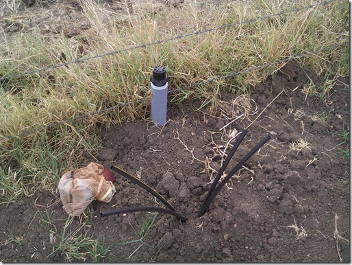
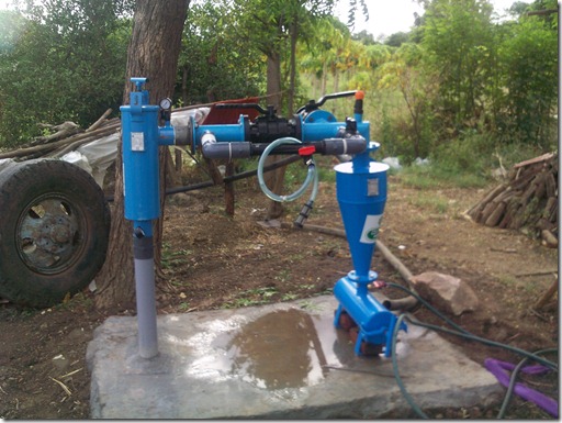
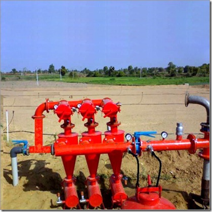
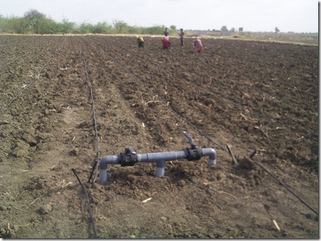
Irrigation and fertigation system
Head Loss & Velocity in Irrigation Pipes
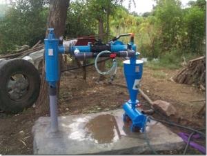
- Actual water requirement of the field
- Available flow of the pump
- Total Head Loss in the system & velocity in irrigation pipes
let’s see them in the brief,
Actual Water Requirement of the field
The first step of drip irrigation design is to calculate the total water required by the area. So how to calculate the water requirement? Let’s take an example,
Suppose we have 1.2 ha area and we are going to grow cotton crop in it at the spacing of 1.40m X 0.40m. We are going to use inline dripper capacity of 2 LPH (litre per hour).
So first thing is how many plants are there in 1.2 ha area? we can calculate it simply by,
1.2 X 10,000 = 12000 sq. meter
now,
= 12000 / 1.40 x 0.4 (Crop spacing)
= 21429 plants in the field
we are going to provide 2 litre water to each plant, so
Total water requirement = 21429 x 2 (Total plants x dripper discharge)
= 42,858 litre or 42.85 m3/hr.
so 1.20 ha are required 42.85 m3/hr. water to irrigate cotton crop.
Available flow of the pump
In the above example we’ve pump of 10 HP and water depth is about 25m. so what is the available flow of the pump set?
well we can calculate it with the device called water meter which is shown below,
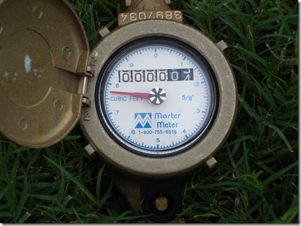
There are many types of water meters available now a days. You can calculate the approximate pump flow with the following formula also.
Pump Discharge = Motor HP X 2.77 X Pump efficiency
Head (m)
“ You can get details on every part of this formula in my previous post”
So we have pump set flow of about 36.93 m3/hr.
we can irrigate the field with maximum of 36.93 cubic meter per hour of water.
To carry these amount of water from water source to the field, we have to consider several things like Head Loss in pipes, Velocity etc.
In drip irrigation system the total head loss in Main line should not be more than 5m and 1.5m in sub main lines. And maximum permissible velocity is 2.0 m/sec.
we can calculate head loss and velocity with "Hazen Williams Formula”
Where,
- Roughness constant for PVC pipe is 150
- Pipe ID = (Pipe OD – Minimum Thickness of pipe) – Maximum Thickness of pipe
Total Head Loss (m) = (Length of pipe (m) X Pressure drop) / 100
Velocity can be calculated by,

As we have seen all this calculation is bit a difficult to do. So i have created an excel sheet for calculating all the data above.
You can download it from Here.
it looks like,
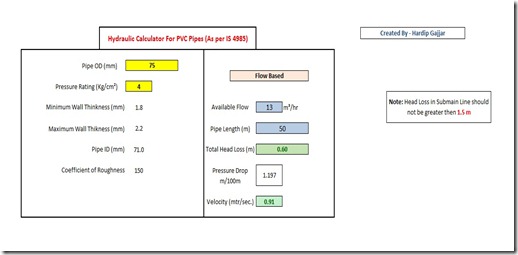
You have to select pipe size and pressure rating from the list,
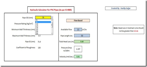
then enter the required flow of the area in the Available flow cell. You can enter the flow in various units like m3/hr., LPM (litre per minute) or LPS (litre per second) select the unit from the drop down list accordingly,
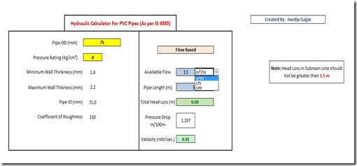
in the next field enter the length of the pipe in metre. As you enter these values it will gives Total Head loss, Pressure Drop and Velocity in the rest of the fields. If the result is according to the criteria ( Head loss not greater than 1.5 in sub main & Velocity not greater than 2.0) the fields are shown in green if the result exceed then it turns red. Which means we have to create a shift in irrigation.
For example,
In this case we have field requirement of 43 m3/hr. and pipe length of about 60 m so what is head loss?
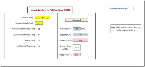
well it is about 6.58 m, which is greater than 1.5m of so it turns red so what we have to do is to irrigate the field in two shifts. So available flow will be 43 / 2 = 21.5 & pipe length will be 60 / 2 = 30m for one shift.
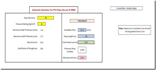
as you notice head loss field turns green. But what about velocity ? it still red ![]()
well it is red because if you are going to design a drip irrigation system for a large area then try to maintain velocity not greater than 1.5 m/sec instead of 2 m/sec of standard recommendations. for this case ignore the velocity of 1.5 m/sec as it is lesser than 2.0 m/sec & our area is small. ![]()
If you are using HDPE Pipes then just scroll down the sheet you will find hydraulic calculator for HDPE pipes,
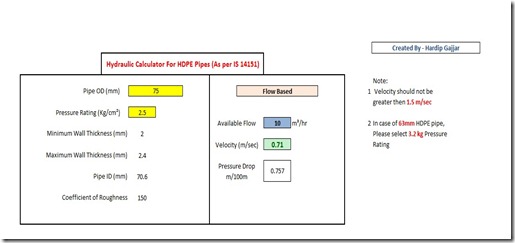
it is velocity based calculator so just enter required flow and select Pipe size and Pressure rating.
As you see all the units are in metric system of measurement. so if you are following units you have to convert the values ![]()
don’t panic just click on the last sheet named “Unit Conversion” here you can convert different units.
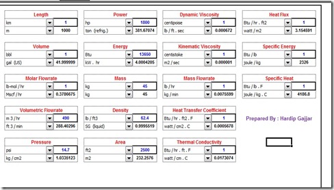
That’s all for hydraulic calculation of irrigation pipes. ![]()
Don’t forget to reply if you have any suggestion
cheers!!
Thanks ![]()
Friday, January 13, 2012
Drip Irrigation Images
Hello everyone!!![]()
In my previous posts I’ve explained too many aspects of drip irrigation system. But as we all know,
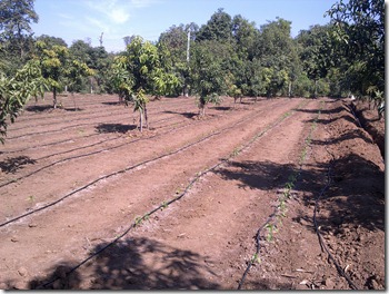
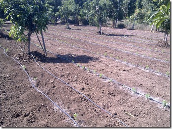
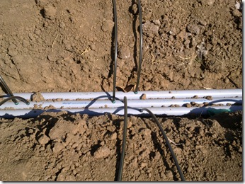
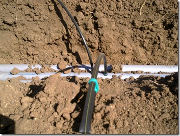
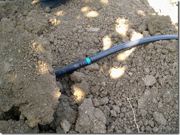
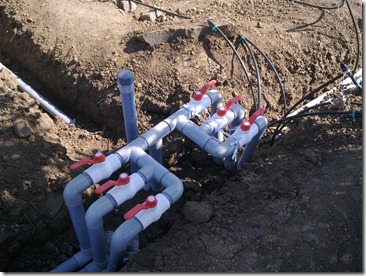
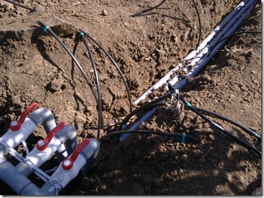
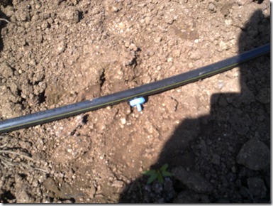
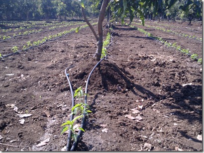
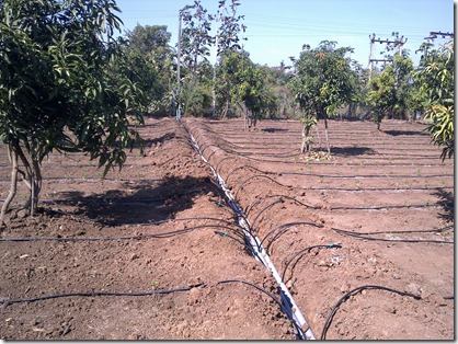
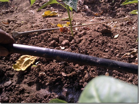
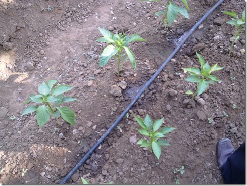
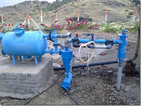
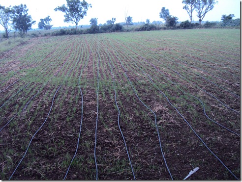
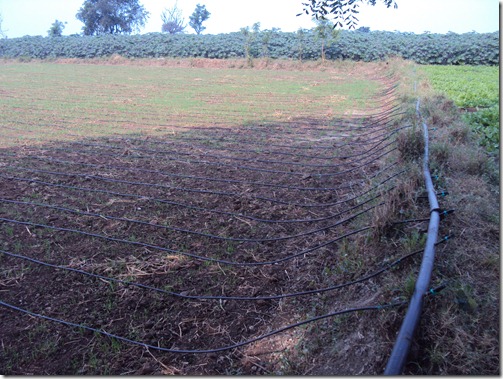
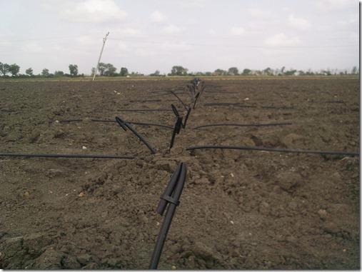
One practical on site is far better then 1 month of learning in the classroom. ![]() So today i have done a little effort to show you the real drip irrigation system on field. Hope you all like it.
So today i have done a little effort to show you the real drip irrigation system on field. Hope you all like it.
- Intercropping in Mango with chillies.
- Component fittings
A small demo for Drip irrigation,
Thanks for watching,


