Heat stress and cooling systems for dairy cows
Automated Control of Shower Cooling
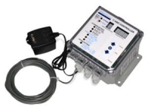
For example, in the LO-Range setting, the user could program the C-400 Controller to commence cooling when temperatures reach 75oF (Actuation Temperature). The controller could activate up to 4 electric valves in sequence, to permit showering for a 2-minute period of time (Shower Time) during a 20-minute cycle. Only one electric valve would be activated at any one time. Thus, with 4 valves, during the 20-minute cycle time, there would be a total of 8 minutes of showering, (2 minutes from each of the 4 valves) followed by 12 minutes with no showering (Interval Time). At the end of this cycle, the controller checks the temperature again, and if the temperature is above the programmed level of 75oF, the cycle will start all over again.
After setting the LO-Range program, the user could set the HI-Range program to begin at temperatures of 85oF or above. In this HI-Range setting, the unit could be programmed to activate each of the electric valves for 1-1/2 minutes of showering during a 10-minute cycle time. This would amount to a total of 6 minutes of showering, (1-1/2 minutes from each of the 4 valves) followed by 4 minutes with no showering. When the temperature drops back below the setting of 85oF, the controller will switch back to the LO-Range program.
 There should be a continuous flow of air over the backs of the cattle any time the cooling system is in operation. This causes the water to be evaporated, which takes the heat away from the cattle in the process. Fans would be controlled separately from the cooling system, and could be set to operate continuously above a temperature of 70oF.
Programming of the C-400 Controller is easy to do. Time and temperature settings in both LO-Range and HI-Range are easily viewed and adjusted as desired. The shower times and interval times can be set anywhere within the range of 0 - 99 minutes, while the actuation temperature can be set anywhere between 40o - 99oF in either the LO or HI-Range settings. You can also select the number of electric solenoid valves that are to be operated. Once the settings are entered, they are saved automatically, and will not be lost if the electrical power is interrupted.
It does not have to be 110oF for heat stress to occur in dairy cows!
 Studies have found that at temperatures as low as 79oF, dairy cows will begin to cut feed intake and lose body weight. Milk production falls. Reproductive performance, health, and lactational performance are affected. Heat stress will continue to affect performance even in the cooler months ahead. High yielding cows are most susceptible to heat stress. All of this quickly impacts your pocket book!
The degree of heat stress suffered by the cow will depend on the combination of environmental conditions - air temperature, relative humidity, air movement, and radiation from the sun. Dairymen use shades, fans, and ample fresh drinking water to help herds beat the heat; but often shade and ventilation are just not enough. In southern states, where heat and humidity are more severe, dairymen have also used sprinklers to provide added cooling effects.
Research has shown that intermittent showering in combination with shade and forced air movement is a very effective method of cooling diary cows, thereby reducing the production losses experienced during hot humid weather conditions. By using a high capacity, coarse droplet shower nozzle, enough water can be applied to fully wet the cows to the hide. The water is then allowed to evaporate, which pulls heat from the animal, just like sweating. Increased air movement across the wet hide provided by fans, makes this system most efficient.
Disadvantages of Misting and Fogging
Mist and fogging nozzles have been used to cool dairy cows, and have proven advantageous in dry climates. They work by cooling the air around the cows. The disadvantage is that the mist can be easily blown away under windy conditions, or when used with fans. If a mist or fog builds up on the cow’s hair coat, it can trap a layer of air between the skin and the water, which holds in body heat. Respiratory problems can also arise if proper ventilation is not provided. In addition mist and fogging nozzles usually must be operated at high pressures and require regular maintenance, especially when poor water quality conditions exist.
In comparison, shower nozzles produce coarse droplet spray which penetrates the hair coat and wets the cow’s skin. To avoid formation of a mist the shower nozzles operate at reduced water pressure of 10-15psi.
Typical Installation of a Shower Cooling System

Normal recommendations are to shower the animals for a short period of time, 0.5 - 3 minutes, to wet the hide. After the shower shuts off, the water is evaporated from the cattle by the air from fans blowing across their backs for 5-15 minutes, before repeating the shower cycle.
The most common locations for installing a shower cooling system are in the holding pen area, where cows are crowded together tightly, and in the feed bunk area. An air velocity of 400-600 ft/min over the cows' backs is recommended. A 36-inch fan providing 11,000 cfm will move air effectively for 20-30 feet, and a 48-inch fan will move air up to 40 feet. Fans should be placed as low as possible, while still allowing clearance for cows and equipment. Nozzles should be mounted just below the fans.
We offer all the components you need to economically set up an intermittent showering system in your facility. The Edstrom C-400 Controller permits you to control up to 4 electric water valves activated in sequence. This electronic controller has a user-programmable thermostat and time settings.
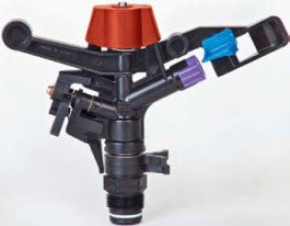
We offer a selection of Shower Nozzles. In addition, an economical 24VAC, 3/4-inch electric valve and filter are offered for installing in your water line. You only need to provide the water distribution pipelines, electrical connections, and the ventilation fans.
The Edstrom Controllers can be ordered with either a 24VAC/110VAC transformer, or a 24VAC/220VAC transformer. This allows you to choose the system that will best fit your operation.
Typical Set Up of a Cooling System
1. First determine where you want to locate the shower nozzles. They should not be installed where they will spray into the feed bunk or a stall area. Common locations are at the feed bunk and in the holding pen areas.

In the holding pen area, full-circle (3600) nozzles are recommended, and should be located to obtain 100% coverage of the area to be sprayed at a height of about 4-1/2 ft. above the floor. At the feed bunk, 1/3-circle (1200) nozzles can be mounted along the top of the bunk head gate and directed to spray out over the backs of the cows
2. Next, determine the plumbing arrangement. This will depend on the quantity and type of nozzles being installed, as well as the water flow capacity of your facility. Multiply the number of nozzles by the nozzles' rated capacity to obtain the total water flow-rate required for the facility. The electric valve-filter-pressure reducer used to control the flow to the nozzles has the capacity to handle up to 15 gpm. If the total flow-rate required for the facility exceeds this capacity, or if the farm water supply is not capable of supplying water at this rate, the nozzle lines need to be divided into sections, or "zones", each supplied by a separate electric valve-filter-pressure reducer. (The C-400 Controller will activate the Electric Valves in sequence; they will not all come on simultaneously.)
When installing the system, locate the electric valve-filter-pressure reducer centrally in each line of nozzles to balance the water pressure to the far end of the lines.
3. The C-400 Controller should be located where it will be easy for the operator to view and make program adjustments. The unit is powered by a 24VAC transformer (included with the controller), which must be plugged into an 110VAC outlet. An optional 220VAC transformer is also available. Electric wiring connects the controller to each electric valve. This is a low-voltage 24VAC circuit. (A 50 ft. roll of low-voltage wire is included with each electric valve kit.)


